imrishabh18/fitness_watch
This circuit integrates an ESP-12E microcontroller with various sensors and peripherals, including a AO3400A MOSFET for switching loads, to enable wireless control and sensor data processing.
- Version
- 1.0.12
- License
- unset
- Stars
- 1
validation/schematic-placement.log
<SchematicBoxPositions>
<SchematicBoxPlacement componentName="U2" positionAnchor="center" schX="-7.5" schY="-2.5" width="4" height="6" />
<SchematicBoxPlacement componentName="J1" positionAnchor="center" schX="16" schY="11" width="2.3" height="1.7" />
<SchematicBoxPlacement componentName="U1" positionAnchor="center" schX="8" schY="11" width="2.8" height="2.1" />
<SchematicBoxPlacement componentName="C4" positionAnchor="center" schX="10.5" schY="8" width="0.9" height="0.6" />
<SchematicBoxPlacement componentName="R4" positionAnchor="center" schX="-3.7" schY="-4.5" width="0.9" height="0.6" />
<SchematicBoxPlacement componentName="R6" positionAnchor="center" schX="-12.5" schY="-3" width="0.9" height="0.6" />
<SchematicBoxPlacement componentName="SW_RST" positionAnchor="center" schX="-14" schY="-5" width="0.94" height="0.719" />
<SchematicBoxPlacement componentName="U6" positionAnchor="center" schX="22" schY="11" width="1.2" height="0.8" />
<SchematicBoxPlacement componentName="R14" positionAnchor="center" schX="-1" schY="-7" width="0.6" height="0.65" />
<SchematicBoxPlacement componentName="R15" positionAnchor="center" schX="17" schY="3" width="0.6" height="0.65" />
<SchematicBoxPlacement componentName="R16" positionAnchor="center" schX="20" schY="3" width="0.6" height="0.65" />
<SchematicBoxPlacement componentName="R17" positionAnchor="center" schX="25" schY="3" width="0.6" height="0.65" />
<SchematicBoxPlacement componentName="C10" positionAnchor="center" schX="11" schY="-12" width="0.6" height="0.65" />
<SchematicBoxPlacement componentName="C11" positionAnchor="center" schX="14" schY="-12" width="0.6" height="0.65" />
<SchematicBoxPlacement componentName="C15" positionAnchor="center" schX="24" schY="-12" width="0.6" height="0.65" />
<SchematicBoxPlacement componentName="C8" positionAnchor="center" schX="8" schY="-15" width="0.6" height="0.65" />
<SchematicBoxPlacement componentName="C9" positionAnchor="center" schX="17" schY="-15" width="0.6" height="0.65" />
<SchematicBoxPlacement componentName="C13" positionAnchor="center" schX="20" schY="-15" width="0.6" height="0.65" />
<SchematicBoxPlacement componentName="C16" positionAnchor="center" schX="27" schY="-15" width="0.6" height="0.65" />
<SchematicBoxPlacement componentName="C12" positionAnchor="center" schX="21" schY="-12" width="0.6" height="0.65" />
<SchematicBoxPlacement componentName="C14" positionAnchor="center" schX="21" schY="-15" width="0.6" height="0.65" />
<SchematicBoxPlacement componentName="Q1" positionAnchor="center" schX="-9.36" schY="-13.5" width="0.68" height="0.4" />
<SchematicBoxPlacement componentName="D2" positionAnchor="center" schX="-12.5" schY="-11" width="1.04" height="0.54" />
<SchematicBoxPlacement componentName="J2" positionAnchor="center" schX="-4.5" schY="-13.5" width="2.5" height="3.4" />
<SchematicBoxPlacement componentName="C6" positionAnchor="center" schX="-11.5" schY="2" width="0.9" height="0.6" />
<SchematicBoxPlacement componentName="C7" positionAnchor="center" schX="-4" schY="2" width="0.9" height="0.6" />
</SchematicBoxPositions>
<SchematicPlacementIssues>
<GenericSchematicBoxTooWide message="Shrink schematic box width" componentName="U2" currentSchWidth="4" measuredInnerLabelHorizontalEmptySpace="3.04" maxAllowedInnerLabelHorizontalEmptySpace="1" suggestedSchWidth="1.96" />
<GenericSchematicBoxTooWide message="Shrink schematic box width" componentName="U1" currentSchWidth="2.8" measuredInnerLabelHorizontalEmptySpace="1.935" maxAllowedInnerLabelHorizontalEmptySpace="1" suggestedSchWidth="1.865" />
<PinHeaderSchematicBoxTooWide message="Shrink schematic box width" componentName="J2" currentSchWidth="2.5" measuredInnerLabelHorizontalEmptySpace="1.735" maxAllowedInnerLabelHorizontalEmptySpace="0.1" suggestedSchWidth="0.865" />
<SchematicPinPaddingToEdgeTooLarge message="Move schematic pins closer to the box edge or change the schematic box height" componentName="U2" pinSide="left" edgeSide="top" pinName="RST" measuredPadding="1.81" maxAllowedPadding="0.2" excessPadding="1.61" suggestedSchHeight="2.78" />
<SchematicPinPaddingToEdgeTooLarge message="Move schematic pins closer to the box edge or change the schematic box height" componentName="U2" pinSide="left" edgeSide="bottom" pinName="VCC" measuredPadding="1.81" maxAllowedPadding="0.2" excessPadding="1.61" suggestedSchHeight="2.78" />
<SchematicPinPaddingToEdgeTooLarge message="Move schematic pins closer to the box edge or change the schematic box width" componentName="U2" pinSide="bottom" edgeSide="left" pinName="CS0" measuredPadding="1.15" maxAllowedPadding="0.2" excessPadding="0.95" suggestedSchWidth="2.1" />
<SchematicPinPaddingToEdgeTooLarge message="Move schematic pins closer to the box edge or change the schematic box width" componentName="U2" pinSide="bottom" edgeSide="right" pinName="SCLK" measuredPadding="1.15" maxAllowedPadding="0.2" excessPadding="0.95" suggestedSchWidth="2.1" />
<SchematicPinPaddingToEdgeTooLarge message="Move schematic pins closer to the box edge or change the schematic box height" componentName="U2" pinSide="right" edgeSide="top" pinName="TXD" measuredPadding="1.81" maxAllowedPadding="0.2" excessPadding="1.61" suggestedSchHeight="2.78" />
<SchematicPinPaddingToEdgeTooLarge message="Move schematic pins closer to the box edge or change the schematic box height" componentName="U2" pinSide="right" edgeSide="bottom" pinName="GND" measuredPadding="1.81" maxAllowedPadding="0.2" excessPadding="1.61" suggestedSchHeight="2.78" />
<SchematicPinPaddingToEdgeTooLarge message="Move schematic pins closer to the box edge or change the schematic box height" componentName="J1" pinSide="left" edgeSide="top" pinName="pin1" measuredPadding="0.85" maxAllowedPadding="0.2" excessPadding="0.65" suggestedSchHeight="0.4" />
<SchematicPinPaddingToEdgeTooLarge message="Move schematic pins closer to the box edge or change the schematic box height" componentName="J1" pinSide="left" edgeSide="bottom" pinName="pin1" measuredPadding="0.85" maxAllowedPadding="0.2" excessPadding="0.65" suggestedSchHeight="0.4" />
<SchematicPinPaddingToEdgeTooLarge message="Move schematic pins closer to the box edge or change the schematic box height" componentName="J1" pinSide="right" edgeSide="top" pinName="pin2" measuredPadding="0.85" maxAllowedPadding="0.2" excessPadding="0.65" suggestedSchHeight="0.4" />
<SchematicPinPaddingToEdgeTooLarge message="Move schematic pins closer to the box edge or change the schematic box height" componentName="J1" pinSide="right" edgeSide="bottom" pinName="pin2" measuredPadding="0.85" maxAllowedPadding="0.2" excessPadding="0.65" suggestedSchHeight="0.4" />
<SchematicPinPaddingToEdgeTooLarge message="Move schematic pins closer to the box edge or change the schematic box height" componentName="U1" pinSide="left" edgeSide="top" pinName="VIN" measuredPadding="0.75" maxAllowedPadding="0.2" excessPadding="0.55" suggestedSchHeight="1" />
<SchematicPinPaddingToEdgeTooLarge message="Move schematic pins closer to the box edge or change the schematic box height" componentName="U1" pinSide="left" edgeSide="bottom" pinName="EN" measuredPadding="0.75" maxAllowedPadding="0.2" excessPadding="0.55" suggestedSchHeight="1" />
<SchematicPinPaddingToEdgeTooLarge message="Move schematic pins closer to the box edge or change the schematic box height" componentName="U1" pinSide="right" edgeSide="top" pinName="VOUT" measuredPadding="0.95" maxAllowedPadding="0.2" excessPadding="0.75" suggestedSchHeight="0.6" />
<SchematicPinPaddingToEdgeTooLarge message="Move schematic pins closer to the box edge or change the schematic box height" componentName="U1" pinSide="right" edgeSide="bottom" pinName="NC" measuredPadding="0.95" maxAllowedPadding="0.2" excessPadding="0.75" suggestedSchHeight="0.6" />
<SchematicPinPaddingToEdgeTooLarge message="Move schematic pins closer to the box edge or change the schematic box height" componentName="U6" pinSide="right" edgeSide="top" pinName="OUT" measuredPadding="0.3" maxAllowedPadding="0.2" excessPadding="0.1" suggestedSchHeight="0.6" />
<SchematicPinPaddingToEdgeTooLarge message="Move schematic pins closer to the box edge or change the schematic box height" componentName="U6" pinSide="right" edgeSide="bottom" pinName="NC" measuredPadding="0.3" maxAllowedPadding="0.2" excessPadding="0.1" suggestedSchHeight="0.6" />
<SchematicPinPaddingToEdgeTooLarge message="Move schematic pins closer to the box edge or change the schematic box height" componentName="J2" pinSide="right" edgeSide="top" pinName="NC1" measuredPadding="0.975" maxAllowedPadding="0.2" excessPadding="0.775" suggestedSchHeight="1.85" />
<SchematicPinPaddingToEdgeTooLarge message="Move schematic pins closer to the box edge or change the schematic box height" componentName="J2" pinSide="right" edgeSide="bottom" pinName="GND" measuredPadding="0.825" maxAllowedPadding="0.2" excessPadding="0.625" suggestedSchHeight="2.15" />
<SchematicBoxInnerLabelCollision message="Inner labels are colliding. Increase the schWidth or schHeight." componentName="Q1" currentSchWidth="0.68" currentSchHeight="0.4" overlappingSides="top,bottom" />
<TraceCanBeSimplifiedByMovingComponent schematicTraceId="schematic_trace_1" targetComponentName="U2" deltaSchX="0" deltaSchY="-1.65" newSchX="-7.5" newSchY="-4.15" currentTurnCount="3" suggestedTurnCount="1" message="move U2 down by 1.65 (to schX=-7.5, schY=-4.15) to reduce this trace from 3 turns to 1" />
<TraceCanBeSimplifiedByMovingComponent schematicTraceId="schematic_trace_9" targetComponentName="R6" deltaSchX="-2.17" deltaSchY="0" newSchX="-14.67" newSchY="-3" currentTurnCount="3" suggestedTurnCount="1" message="move R6 left by 2.17 (to schX=-14.67, schY=-3) to reduce this trace from 3 turns to 1" />
<TraceCanBeSimplifiedByMovingComponent schematicTraceId="schematic_trace_12" targetComponentName="U1" deltaSchX="0" deltaSchY="-3.68" newSchX="8" newSchY="7.32" currentTurnCount="3" suggestedTurnCount="1" message="move U1 down by 3.68 (to schX=8, schY=7.32) to reduce this trace from 3 turns to 1" />
<TraceCanBeSimplifiedByMovingComponent schematicTraceId="schematic_trace_15" targetComponentName="SW_RST" deltaSchX="0" deltaSchY="-9.1" newSchX="-14" newSchY="-14.1" currentTurnCount="3" suggestedTurnCount="1" message="move SW_RST down by 9.1 (to schX=-14, schY=-14.1) to reduce this trace from 3 turns to 1" />
<TwoPinComponentShouldBeVertical componentName="J1" railPin="pin1" railType="power" deltaSchRotation="-90" suggestedRailFacingDirection="up" message="rotate J1 by -90° so its power-connected pin faces up and the component is vertical" />
<TwoPinComponentShouldBeVertical componentName="R14" railPin="pin2" railType="power" deltaSchRotation="90" suggestedRailFacingDirection="up" message="rotate R14 by 90° so its power-connected pin faces up and the component is vertical" />
<TwoPinComponentShouldBeVertical componentName="R15" railPin="pin2" railType="power" deltaSchRotation="90" suggestedRailFacingDirection="up" message="rotate R15 by 90° so its power-connected pin faces up and the component is vertical" />
<TwoPinComponentShouldBeVertical componentName="R16" railPin="pin2" railType="power" deltaSchRotation="90" suggestedRailFacingDirection="up" message="rotate R16 by 90° so its power-connected pin faces up and the component is vertical" />
<TwoPinComponentShouldBeVertical componentName="R17" railPin="pin2" railType="power" deltaSchRotation="90" suggestedRailFacingDirection="up" message="rotate R17 by 90° so its power-connected pin faces up and the component is vertical" />
<TwoPinComponentShouldBeVertical componentName="C10" railPin="pin2" railType="ground" deltaSchRotation="-90" suggestedRailFacingDirection="down" message="rotate C10 by -90° so its ground-connected pin faces down and the component is vertical" />
<TwoPinComponentShouldBeVertical componentName="C11" railPin="pin1" railType="power" deltaSchRotation="-90" suggestedRailFacingDirection="up" message="rotate C11 by -90° so its power-connected pin faces up and the component is vertical" />
<TwoPinComponentShouldBeVertical componentName="C15" railPin="pin1" railType="power" deltaSchRotation="-90" suggestedRailFacingDirection="up" message="rotate C15 by -90° so its power-connected pin faces up and the component is vertical" />
<TwoPinComponentShouldBeVertical componentName="C8" railPin="pin2" railType="ground" deltaSchRotation="-90" suggestedRailFacingDirection="down" message="rotate C8 by -90° so its ground-connected pin faces down and the component is vertical" />
<TwoPinComponentShouldBeVertical componentName="C9" railPin="pin1" railType="power" deltaSchRotation="-90" suggestedRailFacingDirection="up" message="rotate C9 by -90° so its power-connected pin faces up and the component is vertical" />
<TwoPinComponentShouldBeVertical componentName="C13" railPin="pin1" railType="power" deltaSchRotation="-90" suggestedRailFacingDirection="up" message="rotate C13 by -90° so its power-connected pin faces up and the component is vertical" />
<TwoPinComponentShouldBeVertical componentName="C16" railPin="pin1" railType="power" deltaSchRotation="-90" suggestedRailFacingDirection="up" message="rotate C16 by -90° so its power-connected pin faces up and the component is vertical" />
<TwoPinComponentShouldBeVertical componentName="C12" railPin="pin1" railType="power" deltaSchRotation="-90" suggestedRailFacingDirection="up" message="rotate C12 by -90° so its power-connected pin faces up and the component is vertical" />
<TwoPinComponentShouldBeVertical componentName="C14" railPin="pin1" railType="power" deltaSchRotation="-90" suggestedRailFacingDirection="up" message="rotate C14 by -90° so its power-connected pin faces up and the component is vertical" />
<TwoPinComponentShouldBeVertical componentName="D2" railPin="CATHODE" railType="power" deltaSchRotation="-90" suggestedRailFacingDirection="up" message="rotate D2 by -90° so its power-connected pin faces up and the component is vertical" />
<DecouplingCapacitorsNotCloseTogether rail="V3V3" ground="GND" capacitorNames="C4, C11, C9, C13, C12, C14, C6, C7" maxBodyGap="35.724" maxRecommendedBodyGap="4" message="Group the decoupling capacitors between V3V3 and GND closer together in this schematic block. Preserve their net connections." />
</SchematicPlacementIssues>
Related Packages
 More from this authorimrishabh18/boost-converterThis code defines a PCB schematic and 3D model layout focusing on a power conversion circuit with components like USB-C connector, MT3608 step-up regulator, inductor, diode, input/output capacitors, and resistors arranged on a double-layer PCB.
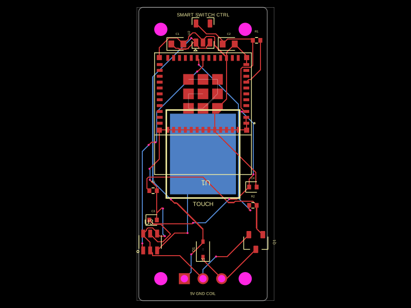 Similar packagehrithik18k/smart-switch-pcbThe AO3400A component models a SOT-23 N-channel MOSFET with labeled pins for Gate, Source, and Drain, including 3D CAD models and schematic symbols for electronic circuit design.
 Discover something newShiboSoftwareDev/mspm0g3507-usb-c-dev-boardThe circuit assembles a USB-C port with integrated ESD protection, power regulation, UART interface, and microcontroller (MSPM0G3507) with supporting components for USB data lines, CC termination, I2C, SPI, reset circuitry, and indicator LEDs.