imrishabh18/pedometer
This code defines and assembles a simple radio receiver hardware circuit using specific imported capacitors, inductors, RF connectors, and oscillator components with precise footprints and schematic attributes.
- Version
- 1.1.3
- License
- unset
- Stars
- 0
docs/firmware-and-bringup.md
# Firmware, BLE and prototype bring-up

## What is implemented

`firmware/pedometer.c` implements BQ25150 initialization/readback, safe OLED power sequencing, SSD1306 initialization and a six-digit step display, Bosch step-counter setup, 24-bit step-counter rollover handling, BQ27427 initial configuration and the BLE snapshot encoder. `app.c` supplies a single-task scheduler: sample every 60 seconds, sample/show on button press, switch the screen off after five seconds, and request a total checkpoint every 15 minutes.

These are **portable C application sources**, not a flashable CC2340R5 firmware image. The TI SDK board/GATT/NVS integration hooks in `board.h` and `app.h` still require implementation and target testing. Host checks cover code logic and mocked register transactions; they cannot establish electrical behavior, radio operation, gauge accuracy or battery life.

The 24-bit sensor count is extended to a 64-bit lifetime total. A counter jump larger than the configured plausibility limit is flagged and rebased, preserving the previous total. The plausibility limit scales with elapsed time at six steps per second plus a margin. Sensor reset/reinitialization must explicitly reset `baseline_valid`. Lifetime count has no date dependency. Daily count and time synchronization are future application features, not silently inferred from uptime.

## TI integration

Use TI's `basic_ble` peripheral example for LP_EM_CC2340R5 in the **SimpleLink Low Power F3 SDK** as the starting project. Select CC2340R52E0RGER (QFN24). Configure the 48 MHz crystal capacitor array for the selected 8 pF crystal and enable the MCU DC/DC power mode. See bare-cc2340r5.md. Configure the external 32.768 kHz clock and the DIO allocation in `interfaces.md`; remove LaunchPad LEDs/buttons/UART mappings that conflict. [TI Basic BLE example](https://dev.ti.com/tirex/explore/content/simplelink_lowpower_f3_sdk_9_14_02_16/examples/rtos/LP_EM_CC2340R5/ble/basic_ble/README.html), [TI SDK introduction](https://software-dl.ti.com/simplelink/esd/simplelink_lowpower_f3_sdk/latest/exports/docs/ble5stack/ble_user_guide/html/quickstart-guide/quickstart-intro-cc23xx.html).

1. Add `app.c`, `pedometer.c` and `vendor/bma400.c` to the application. Configure I2C at 100 kHz and external pull-ups; use a combined write-register/read transaction with repeated START. TI driver APIs usually take **SysConfig indices**, not raw DIO numbers: the board adapter must explicitly map the DIO values from `board.h`.
2. Initialize DISPLAY_ISOLATE HIGH before opening I2C; initialize PMIC_LP LOW. Button input is DIO24, falling edge, with approximately 30 ms software debounce. R6 is the external pull-up. Queue an event from the interrupt; do not perform I2C inside it. Charger and gauge interrupts likewise queue service work.
3. Implement `board_time_ms()` as monotonic 64-bit time. Implement `board_delay_us()` without keeping the MCU awake for long delays; keep the BLE stack serviced. Implement bounded I2C timeouts, serialize access, and return false on NACK/bus failure. Do not hang the task waiting forever for a missing OLED or battery.
4. Restore the saved lifetime total from NVS and call `stride_init(&app, total, wrist)`. If it fails, stay in a fault state with the display isolated; retry after a bounded delay and report diagnostics over SWD during development.
5. In the application task, call `stride_tick()` on queued button/timer events and sleep until `stride_deadline()`. Keep TI's power-management policy enabled so the RTOS can enter standby between events. Calling a busy wait loop defeats the power design.
6. Implement `app_checkpoint()` as a wear-leveled journal with sequence number, payload, CRC and a commit marker written last; recover the newest complete entry. Skip writes when the count is unchanged. A power interruption can lose up to the checkpoint interval. Avoid erasing the same flash sector every 15 minutes.
7. Implement `app_ble_publish()` in the BLE application context. Copy the snapshot, update its GATT value, and notify subscribed clients only when changed. GPIO callbacks and sensor work must not call stack functions from an unsupported context.

## GATT contract

Advertised name: `Stride`. Custom service UUID: `438d0001-0d15-4f45-9b3a-3a4c7942e201`. Snapshot UUID: `438d0002-0d15-4f45-9b3a-3a4c7942e201`, read + notify with CCCD. A 14-byte snapshot fits within the default ATT payload.

| Byte offset | Size | Meaning |
|---:|---:|---|
| 0 | 1 | Version = 1 |
| 1 | 1 | Flags: sensor fault 1, gauge fault 2, counter discontinuity 4, display/PMIC fault 8, persistence fault 16 |
| 2 | 8 | Lifetime steps, unsigned little-endian |
| 10 | 2 | Battery millivolts, unsigned little-endian |
| 12 | 1 | State of charge 0–100, or 255 unknown |
| 13 | 1 | Reserved, zero |

Optionally expose standard Battery Service 0x180F / Battery Level 0x2A19. The included desktop client `companion/read_steps.py` scans for the custom service, reads a snapshot and subscribes. The GATT server must be registered in the TI project before this client can connect. A generic phone BLE explorer can read the same characteristic. Pairing/bonding and a phone UI are not implemented in this prototype core.

## Gauge provisioning

The code verifies device type 0x0427 and only initializes parameters when ITPOR is set. It uses the factory unseal key, enters CFGUPDATE, chooses CHEM_A (4.2 V), then updates State subclass 82 block 0. Fields are **big-endian** within this block: capacity offset 6 = 100 mAh; energy offset 8 = 370 mWh; terminate voltage offset 10 = 3000 mV; taper rate offset 21 = 500 for 2 mA termination; sleep current offset 23 = 10 mA. Command words and ordinary register reads are little-endian. It recalculates the block checksum, checks readback and attempts to exit CFGUPDATE after an update failure. Do not copy BQ27441 offsets into this driver. [BQ27427 Technical Reference Manual](https://www.ti.com/lit/pdf/sluucd5).

The profile is provisional until the exact cell is selected and chemistry compatibility is checked. Defaults are assumed for OpConfig, including sleep mode; read and verify them on hardware. The gauge is left unsealed for development. Reapply configuration after gauge power loss; do not repeatedly overwrite learned RAM at every MCU wake. Adapt the code if production changes unseal keys or battery capacity. Treat battery-low and charger faults as separate conditions; read fault/status registers when servicing their interrupts before implementing a production charge indicator.

## First assembled board

1. Complete the CAD release checks in `validation.md`, verify BGA ball A1 and all power pins against the actual ordered parts, and have the assembler review mask/stencil/via-in-pad requirements. Do not fabricate while trace shorts/clearance errors remain.
2. Start with an adjustable battery simulator/current-limited supply at about 3.8 V and a simulated thermistor at the battery connector. Check for shorts before applying power. Confirm 2.5 V output and isolated OLED I2C. PMIC LSLDO may be at its POR 1.8 V until firmware runs.
3. Connect a 2.5 V-compatible SWD debugger through the five-wire JST-SH adapter on J4, sensing VTREF; use the pin map in `interfaces.md`. Program the integrated TI application. Confirm I2C responses at 0x14, 0x55 and 0x6B with the display off. The OLED should only respond at 0x3C after its power-on sequence.
4. Verify PMIC register readback, 20 mA charge current, 4.20 V regulation, termination and NTC hot/cold charge inhibition using appropriate simulated loads/supplies before connecting the selected real cell. Confirm reset defaults are acceptable for that cell.
5. Walk manually counted trials at slow/normal/fast pace in the intended wear position; test arm gestures, desk vibration, transport and non-walking motion. The hardware algorithm still needs application accuracy validation.
6. Connect BLE, check the 14-byte payload and notification cadence, test button wakes, five-second display timeout, loss/reconnection and power-cycle persistence. Characterize LF clock startup and radio range in the final enclosure.
7. Disconnect debugger, then run the current-profiler and full-discharge tests in `power-budget.md`. Tune power and duty cycles from measurements before calling the weeks target met.
Related Packages
 More from this authorimrishabh18/test-pcmThis code defines a 10mm by 10mm electronic circuit board containing a single pin-row chip with an associated 3D CAD model of the "MachineContactMedium" component.
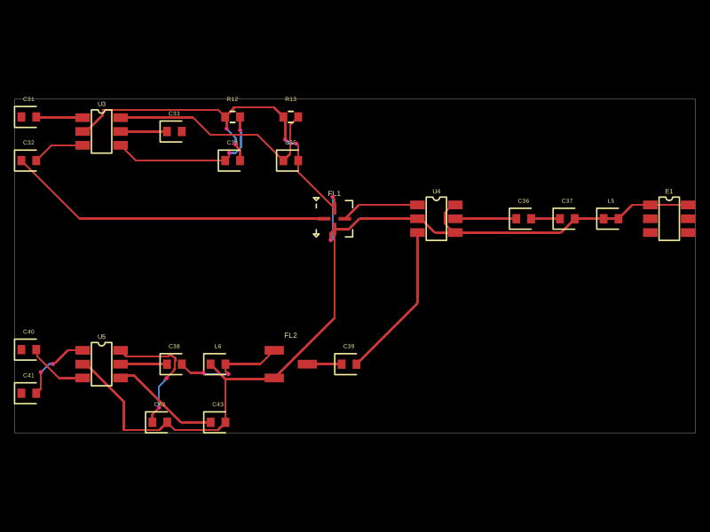 Similar packageMustafaMulla29/CC3235SF-tsxThis code defines a PCB layout with RF front-end components including RF switches (RTC6608OSP), band-pass filters, a diplexer, matching capacitors and inductors, and an antenna, all arranged to match a specific schematic for high-frequency radio signal routing.
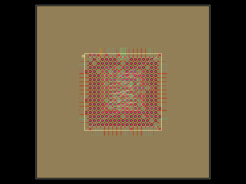 Discover something new0hmX/am3352This code defines a six-layer printed circuit board (PCB) design with a TI AM3352 microprocessor package, including precise pin mapping, power plane definition, fixed component placement, and PCB layout visualization.