imrishabh18/pedometer
This code defines and assembles a simple radio receiver hardware circuit using specific imported capacitors, inductors, RF connectors, and oscillator components with precise footprints and schematic attributes.
- Version
- 1.1.3
- License
- unset
- Stars
- 0
docs/power-budget.md
# Power budget and measurement plan

The baseline estimate uses 100 mAh × 80% usable capacity = **80 mAh**. This reserve is an assumption for cutoff, aging and temperature, not a measured cell characteristic.

| Load | Average current assumption |
|---|---:|
| CC2340R5 standby | 0.71 µA |
| BMA400 100 Hz, normal mode, OSR 0 | 4.0 µA |
| BQ27427 sleep | 9.0 µA |
| BQ25150 battery power-path quiescent | 0.4 µA |
| TPS7A02 no-load quiescent | 0.025 µA |
| Other leakage | 1.0 µA |
| BLE advertising/brief connections | 40 µA budget allowance |
| MCU wake, I2C, processing | 10 µA budget allowance |
| Unmodeled board/cell margin | 25 µA allowance |
| OLED 15 mA, 20 × 5-second wakes/day | 17.36 µA |
| **Total** | **107.5 µA → about 31 days** |

Typical device currents are starting inputs from the manufacturer documentation; BLE, processing and leakage allowances are engineering estimates. The exact radio average depends on advertising interval, transmit power, connection parameters and software. The OLED's current depends strongly on lit pixels and contrast. [CC2340R5](https://www.ti.com/lit/ds/symlink/cc2340r5.pdf), [BMA400](https://www.bosch-sensortec.com/media/boschsensortec/downloads/datasheets/bst-bma400-ds000.pdf), [BQ27427](https://www.ti.com/lit/ds/symlink/bq27427.pdf), [BQ25150](https://www.ti.com/lit/ds/symlink/bq25150.pdf), [TPS7A02](https://www.ti.com/lit/ds/symlink/tps7a02.pdf), [OLED](https://www.adafruit.com/product/4440).

| Scenario | Estimated average | Estimated runtime |
|---|---:|---:|
| Baseline above | 107.5 µA | 31 days |
| Gauge remains near 50 µA rather than 9 µA | 148.5 µA | 22 days |
| OLED uses 30 mA for 5 minutes/day | 194.3 µA | 17 days |
| OLED continuously draws 15 mA | About 15.1 mA | About 5 hours |

Formula: `display_uA = display_mA × 1000 × seconds_per_day / 86400`; `days = usable_mAh / (average_uA / 1000) / 24`.

Start BLE advertising around 2 seconds at 0 dBm. Request a 1-second connection interval, peripheral latency 4 and a supervision timeout comfortably above 10 seconds (for example 12 seconds); the central decides what it accepts. Notify on changed data at the 60-second sample cadence or a user-triggered read. Do not keep a debugging UART or status LED active in the runtime build.

## Measurements that determine whether it really lasts weeks

1. Use a current profiler or shunt instrument at the pack connection. Disconnect SWD and verify display power is off; measure a long enough window to include advertising and 60-second sampling.
2. Separately measure sensor counting mode, gauge sleep/normal state, button handling, I2C bus-low time and display current. Check that disabled OLED bus pins do not back-power it.
3. Confirm the gauge actually enters its intended low-current mode. Its default current deadband is far larger than these microamp loads; reported instantaneous current is not a substitute for a current profiler. Validate accumulated discharge and SOC over several real cycles.
4. Check rail headroom and brownout during BLE plus display at a nearly empty cell. OLED output may enter dropout as the battery approaches 3.3 V; verify usable display voltage and the selected cutoff.
5. Measure at least 48 hours, then run a full discharge under the target usage pattern. For 28 days with 80 mAh usable, average current must be at or below 119 µA; for 21 days, at or below 159 µA.

If an always-visible display is required, revise to a segment LCD or memory display and recalculate the hardware and power budget.
Related Packages
 More from this authorimrishabh18/test-pcmThis code defines a 10mm by 10mm electronic circuit board containing a single pin-row chip with an associated 3D CAD model of the "MachineContactMedium" component.
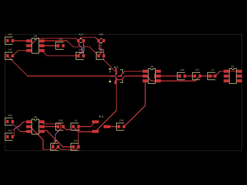 Similar packageMustafaMulla29/CC3235SF-tsxThis code defines a PCB layout with RF front-end components including RF switches (RTC6608OSP), band-pass filters, a diplexer, matching capacitors and inductors, and an antenna, all arranged to match a specific schematic for high-frequency radio signal routing.
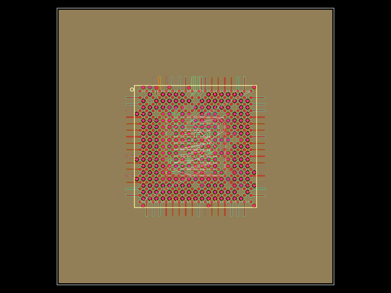 Discover something new0hmX/am3352This code defines a six-layer printed circuit board (PCB) design with a TI AM3352 microprocessor package, including precise pin mapping, power plane definition, fixed component placement, and PCB layout visualization.