rushabhcodes/ESP32-E-Reader
This code defines the physical layout and schematic wiring of an ESP32-based e-reader device, including various surface-mount components such as connectors, ICs, resistors, capacitors, inductors, diodes, pushbuttons, and an antenna, with precise PCB placement and interconnection details.
- Version
- 1.0.8
- License
- unset
- Stars
- 0
imports/SI1308EDL_T1_GE3.tsx
import type { ChipProps } from "@tscircuit/props";

const pinLabels = {
	pin1: ["G"],
	pin2: ["S"],
	pin3: ["D"],
} as const;

export const SI1308EDL_T1_GE3 = (props: ChipProps<typeof pinLabels>) => {
	return (
		<chip
			pinLabels={pinLabels}
			symbol={
				<symbol>
					<schematicpath
						points={[
							{ x: -0.2, y: 0 },
							{ x: -0.08, y: -0.04 },
							{ x: -0.08, y: 0.04 },
							{ x: -0.2, y: 0 },
						]}
						strokeColor="#880000"
						isFilled
						fillColor="#FEFEFE"
					/>
					<schematicpath
						points={[
							{ x: 0.2, y: 0.04 },
							{ x: 0.14, y: -0.06 },
							{ x: 0.26, y: -0.06 },
							{ x: 0.2, y: 0.04 },
						]}
						strokeColor="#880000"
						isFilled
						fillColor="#FEFEFE"
					/>
					<schematicpath
						points={[
							{ x: -0.2, y: 0.14 },
							{ x: 0, y: 0.14 },
							{ x: 0, y: 0.2 },
							{ x: 0.2, y: 0.2 },
							{ x: 0.2, y: 0.04 },
						]}
						strokeColor="#880000"
					/>
					<schematicpath
						points={[
							{ x: -0.2, y: 0 },
							{ x: 0, y: 0 },
							{ x: 0, y: -0.2 },
							{ x: 0.2, y: -0.2 },
							{ x: 0.2, y: -0.06 },
						]}
						strokeColor="#880000"
					/>
					<schematicpath
						points={[
							{ x: 0, y: -0.14 },
							{ x: -0.2, y: -0.14 },
						]}
						strokeColor="#880000"
					/>
					<schematicpath
						points={[
							{ x: -0.24, y: 0.18 },
							{ x: -0.24, y: -0.18 },
						]}
						strokeColor="#880000"
					/>
					<schematicpath
						points={[
							{ x: -0.2, y: 0.18 },
							{ x: -0.2, y: 0.1 },
						]}
						strokeColor="#880000"
					/>
					<schematicpath
						points={[
							{ x: -0.2, y: -0.04 },
							{ x: -0.2, y: 0.04 },
						]}
						strokeColor="#880000"
					/>
					<schematicpath
						points={[
							{ x: -0.2, y: -0.18 },
							{ x: -0.2, y: -0.1 },
						]}
						strokeColor="#880000"
					/>
					<schematicpath
						points={[
							{ x: 0.28, y: 0.04 },
							{ x: 0.24, y: 0.04 },
							{ x: 0.16, y: 0.04 },
							{ x: 0.12, y: 0.04 },
						]}
						strokeColor="#880000"
					/>
					<port
						name="pin3"
						pinNumber={3}
						aliases={["D"]}
						direction="up"
						schX={0}
						schY={0.4}
						schStemLength={0.2}
					/>
					<port
						name="pin1"
						pinNumber={1}
						aliases={["G"]}
						direction="left"
						schX={-0.6}
						schY={0}
						schStemLength={0.2}
					/>
					<port
						name="pin2"
						pinNumber={2}
						aliases={["S"]}
						direction="down"
						schX={0}
						schY={-0.6}
						schStemLength={0.2}
					/>
					<schematicpath
						points={[
							{ x: -0.24, y: 0 },
							{ x: -0.4, y: 0 },
							{ x: -0.4, y: -0.4 },
							{ x: 0, y: -0.4 },
							{ x: 0, y: -0.2 },
						]}
						strokeColor="#880000"
					/>
					<schematicpath
						points={[
							{ x: -0.32, y: -0.06 },
							{ x: -0.36, y: -0.08 },
							{ x: -0.44, y: -0.08 },
							{ x: -0.48, y: -0.1 },
						]}
						strokeColor="#880000"
					/>
					<schematicpath
						points={[
							{ x: -0.4, y: -0.08 },
							{ x: -0.46, y: -0.18 },
							{ x: -0.34, y: -0.18 },
							{ x: -0.4, y: -0.08 },
						]}
						strokeColor="#880000"
						isFilled
						fillColor="#FEFEFE"
					/>
					<schematicpath
						points={[
							{ x: -0.48, y: -0.36 },
							{ x: -0.44, y: -0.34 },
							{ x: -0.36, y: -0.34 },
							{ x: -0.32, y: -0.32 },
						]}
						strokeColor="#880000"
					/>
					<schematicpath
						points={[
							{ x: -0.4, y: -0.34 },
							{ x: -0.34, y: -0.24 },
							{ x: -0.46, y: -0.24 },
							{ x: -0.4, y: -0.34 },
						]}
						strokeColor="#880000"
						isFilled
						fillColor="#FEFEFE"
					/>
				</symbol>
			}
			supplierPartNumbers={{
				jlcpcb: ["C469327"],
			}}
			manufacturerPartNumber="SI1308EDL-T1-GE3"
			footprint={
				<footprint>
					<smtpad
						portHints={["pin3"]}
						pcbX="-0.8001mm"
						pcbY="-0mm"
						width="0.8999982mm"
						height="0.7999984mm"
						shape="rect"
					/>
					<smtpad
						portHints={["pin2"]}
						pcbX="0.8001mm"
						pcbY="0.649986mm"
						width="0.8999982mm"
						height="0.7999984mm"
						shape="rect"
					/>
					<smtpad
						portHints={["pin1"]}
						pcbX="0.8001mm"
						pcbY="-0.649986mm"
						width="0.8999982mm"
						height="0.7999984mm"
						shape="rect"
					/>
					<silkscreenpath
						route={[
							{ x: -0.6999986000000007, y: -1.099997799999997 },
							{ x: -0.6999986000000007, y: -0.6311392000000069 },
						]}
					/>
					<silkscreenpath
						route={[
							{ x: -0.6999986000000007, y: 1.0999977999999828 },
							{ x: 0.09999979999999198, y: 1.0999977999999828 },
						]}
					/>
					<silkscreenpath
						route={[
							{ x: -0.6999986000000007, y: -1.099997799999997 },
							{ x: 0.09999979999999198, y: -1.099997799999997 },
						]}
					/>
					<silkscreenpath
						route={[
							{ x: -0.6999986000000007, y: 0.6311391999999927 },
							{ x: -0.6999986000000007, y: 1.0999977999999828 },
						]}
					/>
					<silkscreenpath
						route={[
							{ x: 0.7999984000000069, y: -1.2999974000000236 },
							{ x: 0.676810019950679, y: -1.1749088714953615 },
							{ x: 0.8012683999999979, y: -1.051083879760526 },
							{ x: 0.9257267800493167, y: -1.1749088714953615 },
							{ x: 0.8025384000000031, y: -1.2999974000000236 },
						]}
					/>
					<silkscreentext
						text="{NAME}"
						pcbX="0mm"
						pcbY="2.0922mm"
						anchorAlignment="center"
						fontSize="1mm"
					/>
					<courtyardoutline
						outline={[
							{ x: -1.4945999999999913, y: 1.3421999999999912 },
							{ x: 1.4946000000000055, y: 1.3421999999999912 },
							{ x: 1.4946000000000055, y: -1.7994000000000057 },
							{ x: -1.4945999999999913, y: -1.7994000000000057 },
							{ x: -1.4945999999999913, y: 1.3421999999999912 },
						]}
					/>
				</footprint>
			}
			cadModel={{
				objUrl:
					"https://modelcdn.tscircuit.com/easyeda_models/assets/C469327.obj?uuid=3848bf4e9fa24fe392fb1bdb7e03bbce",
				stepUrl:
					"https://modelcdn.tscircuit.com/easyeda_models/assets/C469327.step?uuid=3848bf4e9fa24fe392fb1bdb7e03bbce",
				pcbRotationOffset: 90,
				modelOriginPosition: { x: 0, y: 0.000012699999999199463, z: -0.075 },
			}}
			{...props}
		/>
	);
};
Related Packages
 More from this authorrushabhcodes/tetrisThis code defines various electronic component models—including a AAA battery holder, ATtiny85 microcontroller, switch, buzzer, display, and resistors—as hardware modules with detailed footprints, pin configurations, CAD models, and physical specifications for use in circuit design.
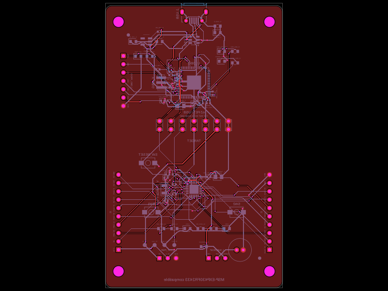 Similar packageShiboSoftwareDev/i-wanThis code defines a PCB and schematic for a microcontroller development board, incorporating various surface-mount components (resistors, capacitors, headers, connectors, crystals, and an IC), with detailed footprints, electrical nets, and routing instructions.
 Discover something newimrishabh18/fitness_watchThis circuit integrates an ESP-12E microcontroller with various sensors, relays, and power management components, including an AO3400A transistor for switching loads, to enable wireless control and sensing functions.